Jeremy's Bearhawk LSA
This is about Jeremy's Bearhawk LSA build. It is from a Quick Build kit from Bearhawk Aircraft.
This is my second homebuilt aircraft. My first was a Zenith CH-750 Cruzer.
Be sure to check out
Build Goals
- VFR (night flight capable): Fun flyer, not serious for travel
- Lightweight: better performance
- Simple: fun, no-frills, easy flying
- Reliable: rather fly than work on it
- Maintainable: when I work on it, make it easy
Resources
This list will grow with time as I discover more resources.
Official Documentation
When purchasing plans you recieve in the mail:
- Blueprints stamped with your serial number
- The Bearhawk LSA Book
- Various full size templates
Other official resources:
Communities
Builder Logs
On the EAA Builders website there are several builders but many seem defunct or just starting, pictures and notes are limited. I have found some that are mature and active.
- Bruce Case - Patrol
- Sergio Desiati
- Richard Tardiff
- Patrick Bruce
- Frank Johnson - LSA, this is his FaceBook page
- Jared and Tabitha's Bearhawk Construction Log
YouTube Videos
Channels showing a large amount of Bearhawk Build videos
- Ken F -- Bearhawk Builder (QB)
- Bearhawk Life -- Bearhawk Builder (QB) -- Completed
- Nev -- Bearhawk Builder (QB) -- Completed
Bearhawk Builders
- Frank Johnson -- Bearhawk LSA (QB)
Individual Videos of Interest
FAA resources
- 43.13B - Acceptable Methods, Techniques, and Practices - Aircraft Inspection and Repair
Other resources of interest
Flight Testing
Commercial
- Aircraft Spruce - Aircraft Part Supplier
- Wicks Aircraft Supply - Aircraft Part Supplier
- Stein Air - Wiring Supplies
- Vetterman Exhaust - Exhaust system built for the Continental O-200 and the LSA.
- Ace Hardware - Various tools and ancilary, non-critical hardware
- Wentworth Aircraft - Various parts
Engine
Thoughts
The Bearhawk LSA was designed to work with Continental 4-cylinder engines anywhere from 65-100hp. Since the original design, others have put on various engines. I really like my ULPower 350iS that I installed on my Zenith CH-750 Cruzer, but it would mean getting involved in making my own cowling/nose bowl as well as engine mount.
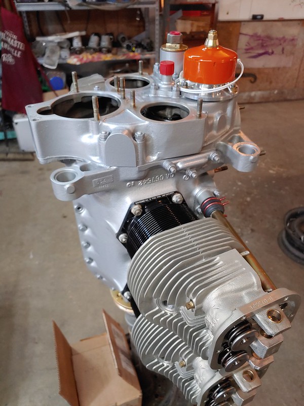
Being that this is going to be a simple build, I opted to go with the design and purchase a rebuilt Continental O-200 from Bob Barrows.
The engine as spec'd includes:
- 8.5 compression ratio
- New Pistons
- Rebuilt Cam and Tappets
- MA3SPA Carburetor
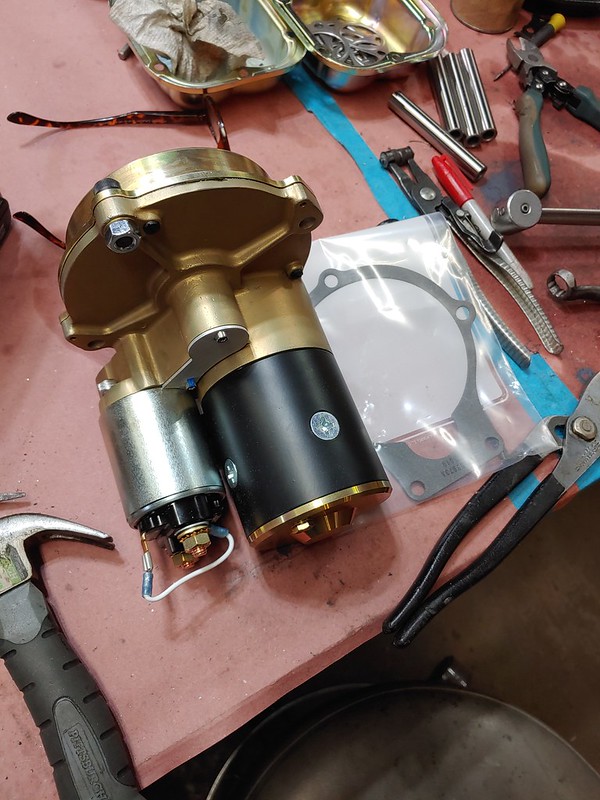
- Lightweight Starter
- Lightweight Alternator
- Lightweight Oil Reservoir
- No magnetos as I'll be using E-mags
Decisions made along the way
- Went with E-mags (P model). Easy install, once engine produces 800 RPM, the E-mags produce their own power, easy timing, auto harness and spark plugs
- Exhaust system with dual mufflers is coming from Vetterman Exhaust
To Be Determined
- Baffling
- Heat Box
Pictures


Electrical
Overview
Device List
| Category | Name | Draw |
|---|---|---|
| Airframe | Landing Light | 3.2a |
| Taxi Light | 3.2a | |
| Strobe Lights | 2.5a | |
| Beacon | ?a | |
| Cabin Light | 0.5a | |
| USB Port | 3a | |
| Avionics | MGL Xtreme EFIS | 200mA |
| iPad Charger | ?a | |
| Trig TY-21 Com Radio | 3.2a | |
| Trig TT-92 Transponder | 3a 1 | |
| Trig TN-72 GPS Receiver | 0.1a | |
| MGL SP-6 Magnetometer | 120mA | |
| MGL SP-7 AHRS | 120mA | |
| MGL RDAC XF | 100mA 2 | |
| Stratux ADS-B Receiver | 1a | |
| Engine | e-mag | 1a 3 |
Switch List
- Master - main power, MGL RDAC, MGL Xtreme EFIS
- Alt. Field
- Avionics Master - all other avionics
- Keyed Mag/Start Switch
- Landing Light (On/Off)
- Taxi Light (On/Off)
- Stroble Lights (On/Off)
- Beacon Light (On/Off)
- Dome Light (On/Off)
- Mag 1 Test (On/Off) -- Maybe push button when pressed is off?
- Mag 2 Test (On/Off) -- Same as Mag 1 Test
Trig TT-92 manual does not specify a current draw but for wiring a 3a breaker is suggested.
2: I did not find the MGL RDAC XF current draw in the MGL manual, I found it on the additional information page for Michigan Avionics.
3: Once the engine RPM is above X RPM the e-Mags produce their own power and no longer draw on alternator or battery.
Device Detail
Wiring
Goals
- Simple
- Engine runs if master is off
- Master switch enables the essential bus for engine startup monitoring
General Notes
Master Bus will power:
- Essential Bus (direct)
- Avionics Bus (through switch)
Essential Bus will power:
- MGL Xtreme EFIS
- MGL RDAC
Avionics Bus will power:
- MGL SP-6 Magnetometer
- MGL SP-7 AHRS
- Stratux ADS-b
- Trig TY-21 Com Radio
- Trig TT-92 Transponder
Nomenclature
Breakers have no pin numbers, but for wiring purposes I'll describe pin 1 as Input and pin 2 as Output.
Switches (typically) do not have pin numbers, but for the purposes of wiring I'll describe pin 1 as the common switched pin, pin 2 as option 1, and pin 3 (if DT) as option 2.
Components
Key
- B: Breaker
- BS: Bus
- S: Switch
- P: Panel Mounted Equipment
- L: Light
- O: Other
List
| Id | Part # | Description | Notes |
|---|---|---|---|
| R:MSTR | Master Relay (Solenoid) | ||
| BS:MSTR | Master Bus | ||
| BS:AV | Avionics Bus | ||
| BS:GND | Ground Bus | ||
| B:MAG1 | E-mag #1 Breaker | 1A | |
| B:MAG2 | E-mag #2 Breaker | 1A | |
| B:LNDGL | Landing light breaker | 5A | |
| B:TAXIL | Taxi light breaker | 5A | |
| B:NAV | Navigation, Position and Strobe lights breaker | 5A | |
| B:ESS | Essential Bus Breaker | 2.5A | |
| B:AV | Miscellenaeous Avionics | 2.5A | |
| B:COM | TY-21 | 5A | |
| B:XPDR | TT-92 | 5A | |
| B:AUX | Auxiliary, Dome, USB Charger | 5A | |
| S:MSTR | Master Power | SPST | |
| S:AV | Avionics Master | SPST | |
| S:LANDL | Landing Light | SPST | |
| S:TAXIL | Taxi Light | SPST | |
| S:STBL | Strobe Lights | SPST | |
| S:POSL | Naviation/Position Lights | SPST | |
| S:BCNL | Beacon Light | SPST | |
| S:DOML | Dome Light | SPST | |
| P:XTRM | MGL Extreme EFIS | ||
| P:TY21 | Trig TY-21 Com Radio (head) | ||
| O:TY21 | Trig TY-21 Com Radio (remote) | ||
| P:TT92 | Trig TY-92 Transponder (head) | ||
| O:TT92 | Trig TY-92 Transponder (remote) |
CAN Bus Flow
- RDAC
- EFIS
- SP-6
- SP-7
Master Wiring List
| X | Source | S. Label | Wire | D. Label | Destination |
|---|---|---|---|---|---|
| Power | |||||
| Bat + | R:MSTR:IN | ||||
| Bat - | Firewall Lug | ||||
| R:MSTR:OUT | BS:MSTR:IN | ||||
| EFIS | |||||
| BS:MSTR | EFIS Brkr | Pwr | B:ESS | ||
| B:ESS | EFIS Pwr | 22 | Pwr | 1 | |
| BS:GND | EFIS Gnd | 22 | Gnd | 3,4,9,10 | |
| RDAC | |||||
| B:ESS | RDAC Pwr | 22 | Pwr | 8 | |
| BS:GND | RDAC Gnd | 22 | Gnd | 5 | |
| SP-6 | |||||
| B:AV | SP6 Pwr | 22 | Pwr | 6,7 | |
| BS:GND | SP6 Gnd | 22 | Gnd | 1,2 | |
| SP-7 | |||||
| B:AV | SP7 Pwr | 22 | Pwr | 6,7 | |
| BS:GND | SP7 Gnd | 22 | Gnd | 1,2 | |
| CAN Bus | |||||
| RDAC | |||||
| 6 | CAN Bus (HI) | 22^W/B | RDAC CB (HI) | EFIS.12 | |
| 7 | CAN Bus (LO) | 22^W | RDAC CB (LO) | EFIS.13 | |
| EFIS | |||||
| 12 | CAN Bus (HI) | 22^W/B | SP6 CB (HI) | SP6.9 | |
| 7 | CAN Bus (LO) | 22^W | SP6 CB (LO) | SP6.8 | |
| SP6 | |||||
| 9 | CAN Bus (HI) | 22^W/B | SP7 CB (HI) | SP7.9 | |
| 8 | CAN Bus (LO) | 22^W | SP7 CB (LO) | SP7.8 | |
| EFIS | |||||
| 2 | ALARM | 22^W | ALARM - | ALARM ANNUNCIATOR | |
| 11 | OAT | 22^G | EFIS | OAT Red | |
| 7 | GPS TX | 24^W | ELT | ? | |
| GPS | GPS ANT | GPS Ant |
Configuration
MGL Xtreme EFIS
- Menu
- GPS Setup
- NMEA Output: RS232 COM1
- NMEA Baud Rate: 9600
- CO Monitor Setup
- CO Monitor: CO GUARDIAN - RS232 COM2
- GPS Setup
TODO
- Alarm Annunciator Light
Avionics
Decision Process
Needs/Goals
I want a simple aircraft, thus simple instrumentation, however modern avionics provide quite a bit of situational awareness and safety. Strike a balance between simplicity and safety.
- Single Radio is fine, monitoring of a second frequency would be nice.
- Single Radio, only 1 passenger means simple intercom is fine.
- Since there is a power source, the transponder needs ADS-B out capability.
- ADS-B in capability provides too many benefits and increases safety enough that I want it.
- Engine monitoring and logging can make maintenance easier and flying safer.
Considerations
- Garmin/Dynon/MGL/GRT Glass Panels: My Zenith Cruzer CH-750 has a light IFR panel w/G3X at the heart of it. I very much enjoy this setup, but for my needs/goals a full glass setup is overkill.
- Steam Gauges: Simplicity, but some glass interfaces provide too much safety/situational awareness to ignore.
- MGL Blaze Gauges: While they provide more functionality than steam gauges, they do not provide the situational awareness I am looking for.
Decision
- MGL Xtreme Mini EFIS — EFIS
- Apple iPad Mini — Mapping, Weather, Traffic
- Trig Avionics TY-91 — Radio/Intercom
- Trig Avionics TT-22 — Transponder with ADS-B Out
With these four devices, the only other thing on the panel will be switches, breakers and engine controls!
MGL Xtreme Mini EFIS
MGL Xtreme Mini EFIS. With the addition of the MGL SP-6 (magnetometer), MGL SP-7 (AHRS), and MGL RDAC XF, this device becomes an all in one device for all air and engine instruments. Further, it has basic GPS navigation capabilities.
- Primary EFIS including:
- Attitude
- Magnetic Heading
- Altimeter
- Airspeed
- Vertical Speed
- Slip/Skid Indicator
- Primary Engine Information including:
- RPM
- Oil Pressure
- Oil Temperature
- CHT Temperatures
- EGT Temperatures
Futher, it has advanced features such as:
- Heading Bug
- Altitude Bug
- Density Altitude
- Outside Air Temperature
- Timer
- Flight Logging
- True Airspeed Calculation
- G-Force Meter
- Wind Speed and Direction Display
- GPS Navigation
- CDI
- Simple Point to Point
- Route Capable
- POIs loaded for all FAA points
- Can drive 2 MGL Autopilot Servos directly
- Fuel Flow
- Lean Assist
- Alarms for most parameters
- User defined checklists
- Data Logging
Apple iPad
Will have a mount that the iPad can be easily removed. Will be running software such as ForeFlight that is linked to an external ADS-B receiver source. Will be responsible for mapping, weather and traffic.
Trig Avionics
Both devices have the same profile and general use. Both have remote mounted electronics to make the actual installation in the panel very easy and clean. Further, they are light weight.
Trig TY-91 Radio
This provides a radio with monitoring capability and a build in intercom. The build in intercom further reduces complexity and weight.
Trig TT-22 Transponder
When coupled with a TN-72 GPS source, the Trig TT-22 provides a simple transponder with ADS-B out.
Panel Layout
Thoughts
Since the throttle is on the left
- I will fly with my right hand more
- With throttle friction lock, my left hand will be more free
- Place instruments I change more on the left
- Place instruments I change less (display mainly?) on the right
- Place the key switch on the right so I can have my hand on the throttle while starting
Segregate switches into two groups
- Those I use on the ground such as Master, Alternator, Avionics Master, Engine Start/Mag Selection, Beacon Light
- Those I use in the air such as Navigation Lights, Strobe Lights, Landing Light, Taxi Light, Dome Light
This means I am less likely to flip a wrong switch, or worst case scenario if I do flip an "in-flight" switch, nothing bad will happen.
MGL Xtreme EFIS
Combined EFIS/EMS for an all-in-one Primary Instrument.
Resources
- Manufacturer Website
- Manual: MGL/Xtreme EFIS Manual G2.pdf
- Drawing: MGL/Xtreme EFIS Dimensions G2.pdf
Technical Information
- DB15 Connector
- 1A current draw
Pin Information
The unit has only one connector, a DB15
| Pin | Description |
|---|---|
| 1 | 8-30Vdc |
| 2 | Alarm Output |
| 3,4,9,10 | Ground |
| 5 | RS232 Port 2 TX |
| 6 | RS232 Port 2 RX |
| 7 | RS232 Port 1 TX |
| 8 | RS232 Port 1 RX |
| 11 | OAT Probe |
| 12 | CAN bus High |
| 13 | CAN bus Low |
MGL SP-6
Remote mount magnetometer
Resources
- Manufacturer Website
- Manual: MGL/SP6-SP7.pdf
Technical Information
- DB9 Female Connector
- 50ma current draw
- 120ma current draw with internal heater on
Pin Information
The unit has only one connector, a DB15
| Pin | Description |
|---|---|
| 1,2 | Ground |
| 3 | RS232 RX |
| 4 | RS232 TX |
| 5 | MGL Airtalk |
| 6,7 | +8-20V |
| 8 | CAN Low |
| 9 | CAN High |
MGL SP-7
Remote mount AHRS
Resources
- Manufacturer Website
- Manual: MGL/SP6-SP7.pdf
Technical Information
- DB9 Female Connector
- 50ma current draw
- 120ma current draw with internal heater on
Pin Information
The unit has only one connector, a DB15
| Pin | Description |
|---|---|
| 1,2 | Ground |
| 3 | RS232 RX |
| 4 | RS232 TX |
| 5 | MGL Airtalk |
| 6,7 | +8-20V |
| 8 | CAN Low |
| 9 | CAN High |
MGL RDAC XF-MAP
Engine monitoring module
Resources
- Manufacturer Website
- Manual: MGL/RDAC XF INSTALLATION.pdf
Technical Information
- DB9 Female Connector
- 50ma current draw
- 120ma current draw with internal heater on
Pin Information
The unit has only one connector, a DB15
| Pin | Description |
|---|---|
| 6 | CAN High |
| 7 | CAN Low |
| 8 | +12V |
| 9 | Ground (Engine Block) |
Trig TT-22
Resources
- Manufacturer Website
- Installation Manual: Trig Avionics/00560-00 AQ TT21TT22 Installation Manual.pdf
- Operating Manual: Trig Avionics/00559-00-AG TT21TT22 Operating Handbook.pdf
Technical Information
- 11-33v
Pin Information
The TT-22 is actually two components, a remote mount module and a control head. I will identify the ports as TTCH.# for the Control Head and TT.# as the main module.
Module
| Pin | Description |
|---|---|
| 1 | Ground |
| 2 | TMAP1A - Control Head Communication |
| 3 | TMAP1B - Control Head Communication |
| 4 | Ground |
| 5 | GPS Position In |
| 6 | Ground |
| 10 | Ground |
| 11 | Controller Power |
| 12 | Power Ground |
| 13 | Power ON |
| 14 | Ground |
| 15 | 11-33V DC |
Control Head
| Pin | Description |
|---|---|
| 1 | Ground |
| 2 | TMAPA - Control Head Communication |
| 3 | TMAPB - Control Head Communication |
| 6 | Ground |
| 7 | Remote ON |
| 8 | Power |
| 9 | Ground |
Trig TN-72
GPS Position Source
Resources
- Manufacturer Website
- Installation Manual: Trig Avionics/01691-00 AI TN72 Installation Manual
Technical Information
- 11-33v
- DB9 Male Connector
Pin Information
The unit has only one connector, a DB9. Only pins of interest are listed here
| Pin | Description |
|---|---|
| 1 | Power |
| 2 | Ground |
| 7 | RS232 GPS TX |
Trig TY-91
Compact VHF Tranciever
Resources
- Manufacturer Website
- Installation Manual: Trig Avionics/00839-00-AG TY9x Installation Manual.pdf
- Operating Manual: Trig Avionics/00840-00-AD TY91 and TY92 VHF Radio Operating Manual
Technical Information
- 11-33v Input
- 3.2A maximum current (pg 6 installation manual)
- DB25 Male Connector
- 5A circuit breaker is suggested for power (pg 20 installation manual)
- 20G wire is suggested for power (pg 21 installation manual)
Pin Information
The TY-91 is actually two components, a remote mount module and a control head. The Trig manual references the control head as TC90, thus pins will be identified as TC90.# for control head, and TY91.# for the main module.
Main Module
Module contains a DB-25, Male Connector. Harness will need a DB-25 Female. I have only listed the pins of interest for my installation.
| Pin | Description |
|---|---|
| 3 | TMAP1A - Control Head communication |
| 4 | TMAP1B - Control Head communication |
| 9 | Ground |
| 10 | Headphone Ground |
| 11 | Headphone Out |
| 12 | Controller Power (remote head) |
| 13 | Power On |
| 14 | PTT Key 2 |
| 15 | PTT Key 1 |
| 17 | Intercom Key |
| 19 | Ground |
| 20 | Aux Audio |
| 21 | Microphone 2 |
| 22 | Ground |
| 23 | Microphone 1 |
| 24 | Aircraft Power |
| 25 | Aircraft Power |
When the Intercom Key (#17) is grounded, the intercom is enabled. Some place a switch to enable or disable the intercom, others ground it directly and the intercom is always enabled.
Control Head
Control Head contains a DB-15 Male. Harness will need a DB-15 Female.
| Pin | Description |
|---|---|
| 2 | TMAPA - Remote Module |
| 3 | TMAPB - Remote Module |
| 8 | Remote ON |
| 9 | Power IN |
| 10 | Power Ground |
Tasks
See also Decisions to be made. Tasks are created once something concrete is known that needs to be done.
Figuring
- Determine Engine Mount -> Engine, what do we need?
- Determine what to do about an airbox
Shopping List
- Exhaust Gasket(s)
- ELT-04 ELT (wait to purchase until needed due to expiring battery)
- EarthX ETX-680 Battery (wait to purchase until needed)
- EarthX ETX-680 Battery Tray
- 4x AN5-35A for Engine Mount to Fuselage
- 50x AN3-3A for firewall and spares
- 50x AN365-1032
Administrative
- Builder Plate (use same guy who made mine for N622JC)
Completed
Administrative
2/15/2022
- Determine what N-number I wish to reserve -- N67BH, reserved
Shopping
2/25/2022
- Magneto gears from Wentsworth Aircraft
2/16/2022
Aircraft Spruce, I probably ordered too many, but can you have too many? :-)
- 50x 3/4 Adel Clamps
- 50x 5/8 Adel Clamps
- 10x 3/16 Adel Clamps
- 50x 5/16 Adel Clamps
- 1x ACS Key Switch
2/14/2022
Orders from EAA, Aircraft Spruce, Ace Hardware and Amazon
Ace Hardware
- 100 pack 8-32 1/2" Stainless
EAA
- EAA Registration Guide $
- EAA Flight Test Handbook $
Aircraft Spruce
- Tube bender $$
- Tube flairing tool $$ (Backordered)
- 25x AN364-1032A
- 25x AN364-428A
- 25x AN364-524A
- 4x AN4-26 - Brake Pedals
- 4x AN5-24 - Landing Gear Leg
- 2x AN7-20 - Shocks -> Gear Leg
- 2x AN7-13 - Shocks -> Fuselage
- 25x AN7 Castle Nuts
- 25x AN6 Castle Nuts
- 25x AN5 Castle Nuts
- 25x AN4 Castle Nuts
- 25x AN3 Castle Nuts
- Cotter Pin Assorment Kit
- Aircraft Logbook $
- Engine Logbook $
- Propeller Logbook $
- 2x Stick Grips $$ (https://www.aircraftspruce.com/catalog/elpages/taeakwoodgripstandard.php)
- 3/16", 1/4", 5/16" and 3/8" Reamers
Amazon
- 2x 12V USB power outlet
- 2x Bus Bar (Positive and Ground)
- Viz-Torque
About
I create a build log for each session. In the left menu, I place the most recent build log entries first for easy access. It does make things appear in a "backwards" order, but I do believe it is easier to see progress this way.
Build Sequence/Milestones
This is a list of major tasks and build sequence according to the Bearhawk Manual.
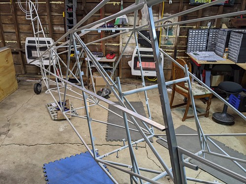
Fuselage
- ☑ Assemble Shocks
- ☑ Install brake calipers
- ☑ Attach landing gear
- ☑ Install wheels and tires
- ☑ Install tailwheel spring
- ☐ Install rudder pedal assembly (waiting on right pilot rudder pedal)
- ☑ Install control stick assembly
- ☑ Install fuselage stringers
- ☑ Fit and install floor boards
- ☑ Install seats
- ☐ Fabricate door skins
- ☐ Install doors
- ☐ Install rear windows
- ☑ Install firewall
- ☐ Fabricate/install rear cargo bulkhead
- ☐ Fabricate/install instrument panel
- ☐ Install instruments and wiring
- ☐ Install tail and tail struts
- ☐ Run control cables and pulleys
- ☐ Run fuel lines and fuel valve
- ☐ Install Fuel Valve
- ☐ Install Gascolator
- ☐ Install trim system
- ☐ Torque all bolts
- ☐ Install motor mount
- ☐ Fabricate/install boot cowl
- ☐ Install brake reservoir, master cylinders
- ☐ Run brake lines
- ☐ Install windshield
- ☐ Install engine, prop and spinner
- ☐ Install covering
Right Wing
- ☑ Unpack wing
- ☑ Drill out pop rivets
- ☐ Install alieron actuation system
- ☐ Install ailerons
- ☐ Install fuel tanks and fuel lines
- ☐ Run electrical conduits
- ☐ Torque all bolts
- ☐ Install stiffeners at trailing edge
- ☐ Rivet top skins
- ☐ Install aileron pocket skin
- ☐ Rivet tank bay stiffeners
- ☐ Finish access panels
- ☐ Install wing tip
Left Wing
- ☐ Unpack wing
- ☐ Drill out pop rivets
- ☐ Install alieron actuation system
- ☐ Install aileron
- ☐ Install fuel tank and fuel lines
- ☐ Run electrical conduits
- ☐ Plumb pitot tube
- ☐ Torque all bolts
- ☐ Install stiffeners at trailing edge
- ☐ Rivet top skins
- ☐ Install aileron pocket skin
- ☐ Rivet tank bay stiffeners
- ☐ Finish access panels
- ☐ Install wing tip
Finishing Sequence
- ☐ Set incidence and finish drilling wing fittings
- ☐ Set dihedral and drill struts
- ☐ Hang wings
- ☐ Connect wing fuel lines to fuselage
- ☐ Make wing/fuselage fairings
- ☐ Make tail/fuselage fairings
- ☐ Fabric on seats
- ☐ Paint boot cowling
- ☐ Paint wings
- ☐ Reassemble
- ☐ Fly
Known Tasks
In Progress and On Going
- Wiring Diagram
- Panel Design
Can Act On Now
- Rear windows
- Fuel lines
- Replace hardware with correct hardware. Sometimes I do not have the right piece of hardware, a bolt too short or too long, one that needs drilled or not drilled, etc. I use temporary hardware to fit things and determine what the proper hardware is, then order.
- Control stick
- Landing gear leg to fuselage
- Mount lower instrument panel
- Start playing with the boot cowl
On Hold
- Pick colors for Oratex fabric order
- Talked with Oratex on Friday, 2/25. They sent a quote, we are going to request fabric samples on Monday then hopefully make a decision by end of week.
Solved, Can Act On Now
Future
Things to Remember
Bolts
| Location | Bolt | Nut | Count | Torqued |
|---|---|---|---|---|
| Gear | ||||
| Brake Caliper Mount → Landing Gear | AN4-4A | AN365/364 | 8 | yes |
| Tailwheel Spring → Tail Wheel | AN4-14A | AN365 | 2 | yes |
| Tailwheel Spring → Fuselage | AN4-15A | AN365 | 1 | yes |
| Wheel Halfs | Supplied | Supplied | 12 | yes |
| Brake Disc to Wheel | Supplied | Supplied | 6 | yes |
| Shock → Landing Gear | AN6-20 | AN310 | 2 | no |
| Shock → Fuselage | AN6-13 | AN310 | 2 | no |
| Control Stick | ||||
| Sticks → Interconnect Tube | AN3-5A | AN364 | 2 | no |
| Sticks → Torque Tube | AN3-23 | AN320 | 2 | no |
| Firewall | ||||
| Mounting | AN3-3A | AN365 | 11 | no |
| Miscellaneous | ||||
| Floor Boards | 8-32 S 1/2" | |||
| Right Wing | ||||
| Top Rear Tank Straps | AN3-5A | AN365 | 2 | yes |
| Bottom Rear Tank Straps | AN3-6A | AN365 | 2 | yes |
| Front Tank Staps | AN3-6A | AN365 | 4 | yes |
Guide
- Bolts with trailing A = Non-drilled
- Bolts with no trailing A = Drilled
- AN310 = Castle Nut
- AN315 = Check Nut
- AN316 = Thin Check Nut
- AN320 = Shear Castle Nut
- AN364 = Shear Elastic Nut
- AN365 = Elastic Nut
Other Fasteners
| Location | Note |
|---|---|
| Wing Tank Strap | Allen Head = 5/32" |
Places to Revisit
Scratched Paint, Re-prime for protection
- Pilot side, top stringer, rear bulkhead upright, picture 2/20/2022 at 3:24PM
- Passenger side, top stringer c-clip. I let the bit walk a bit and get too close to the edge for proper edge distance. Thus I abanoned my start and put a rivet in the rear of the clip.
Rough Area that will come in contact with Fabric
- Top stringer, mid-fuselage, picture 2/20/2022 at 3:27PM
Notes
Wings
- All tank straps had bolts in place. Right Wing, Top Rear were too small, no threads showing through bolt. All others were a tad too long, but not enough to make me replace them. All that I left in place were checked for proper torque.
Checklist Items
- Fuel Cap Vent Hole is facing forward.
Build Log - 2022
While 2021 was about finishing the Zenith CH-750 Cruzer and planning/acquiring the Bearhawk LSA, 2022 is when the work actually has begun.
February
Total Time: 3h0m0s
The month of February 2022 is the month the actual build began. Time not included here is getting the shop set back up. Most of my tools, shelves, etc. were moved to the hangar to finish the Zenith CH-750 Cruzer build. We were anxious to get started so we took the slower, but immediate gratification route, of moving only the base tools necessary from the hangar to the garage and piling them in a corner :-/. As we needed a tool, we used it, then put it back in a better place. If we didn't have the tool in the garage, we made another trip to the hangar bringing back another load of tools.
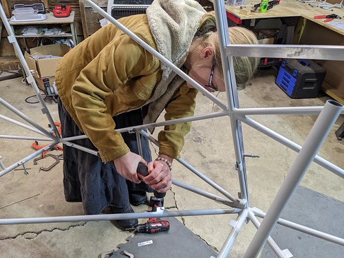
Sunday, February 27th, 2022
Time: 2.5h
- Study plans, manual and Bearhawk Tips to understand the fuel line installation
- Al came over to see the Bearhawk LSA
- Replace control bolts/nuts with proper hardware
- Lucas came over to teach me techniques for flairing fuel lines.
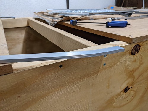
- Made a few practice flairs in the fuel line. Turns out the flairing tool is chewing up the 3003 aluminum. No acceptable flair was created.
Useful Resources
- Bearhawk Tips
Photo Stream
Flairs created by my flairing tool

Saturday, February 26, 2022
Time: 4h
- Worked on wiring diagram. Playing with tool called WireViz. I created the wiring diagram for the Trig TT-22 Transponder, TN-72 GPS Source and TC-20 Control Head.
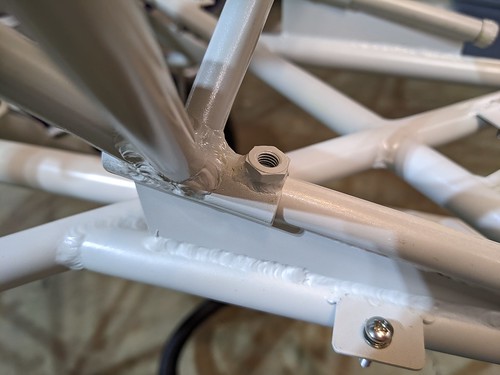
- Spent 45 minutes or so figuring out the heim join for the aileron push rod to aileron connection. They don't make a heim joint that meets the requirements. The fittings on the aileron need to have a joggle put in them to accept a wider heim join, per Mark.
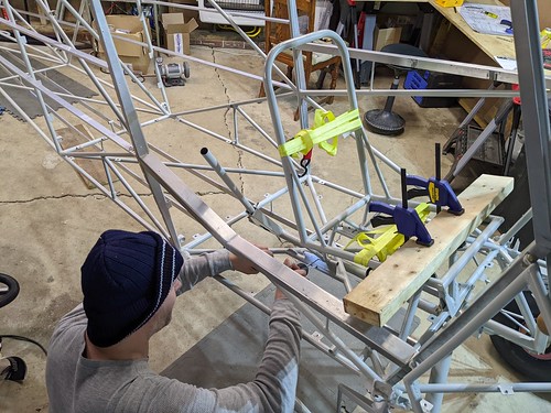
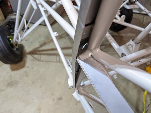
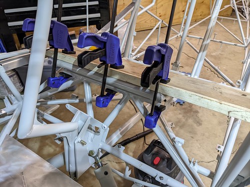
- Attached front of the 4 side stringers
- Began working on how rear windows will mount
- Put joggles in the aileron mount per Mark so the alieron push rod heim join will attach properly
Notes
- Determine proper heim join for the aileron push rod. The ones that came with the kit are the right thread but the heim join is too wide.
- The right width of the heim join is 5/16" (0.312", 7.9mm). The thread should be 1/4" 28. The width of the only heim join in the kit with 1/4" 28 thread is 7/16" (0.4345"). The kit did come with hiem joins that has a width of 5/16" but they are 10-32 thread. For Aurora Bearings they make an MM3 that is the right width but it is 10-32 thread. MM-4 is 1/4" 28 thread but 0.375" wide. I can not find a 5/16" width with a 1/4" 28 thread.
- Contacted Mark for help.
- Mark said the proper heim joint does not exist. On the aileron fitting you need to put a slight joggle in both brackets to accept the larger heim joint.
Photo Stream
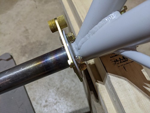
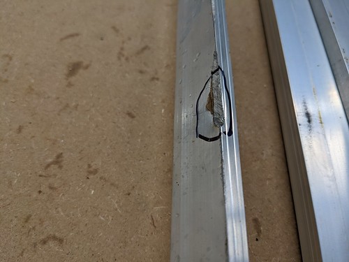
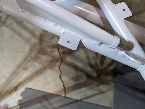
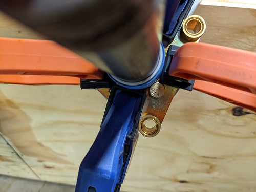
A proper fitting heim joint
This heim joint, though, is 1032 not 1/4 28 as needed by the push tube. The proper heim joint does not exist, thus the aileron bracket needs to have a joggle in both sides to move it from 0.312" to 0.375" width.

The most narrow 1/4 28 heim joint
Need to modify the bracket to accept.

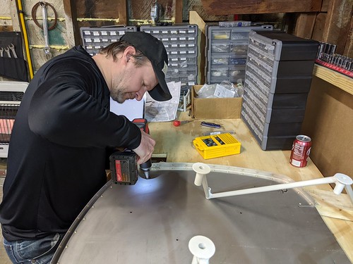
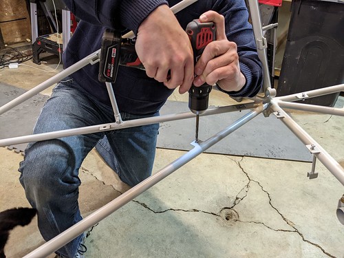
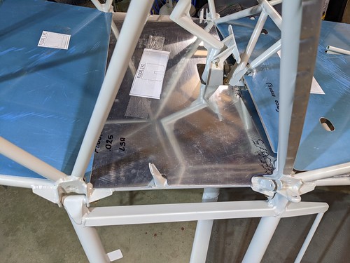
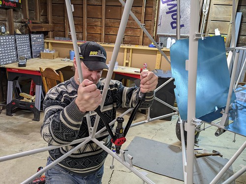
Drilling out the temporary rivets to allow access to mount 4 front/side stringers

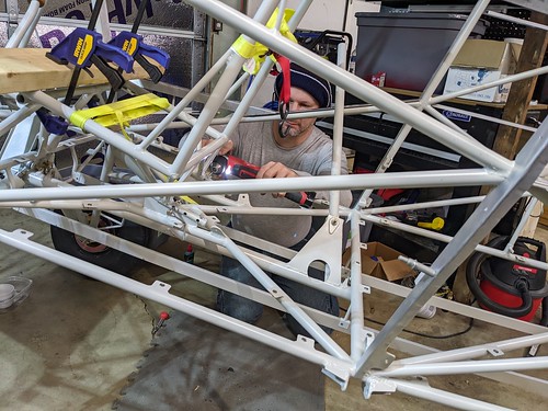
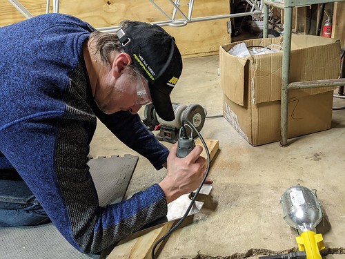
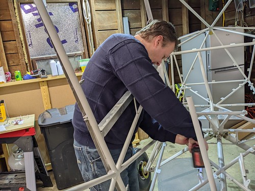
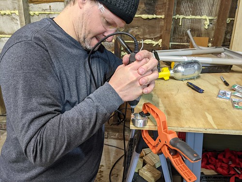
Modified rivet gun
Building a Zenith previously, we went through a few hand rivet guns even though the majority of the work was done with an air rivet gun. This one has served me well, even after grinding a lot of it away to fit in tight spots such as this one. Bought from my local Ace Hardware, a Stanley.

Ground in multiple places
The head is ground on three sides to fit close to other objects. The frame being ground is a new one for the Bearhawk to allow me to rivet closer to a tube.
We're not pulling big, heavy steel rivets, just small stuff.

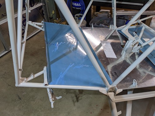
Bevel in
I was thinking this would be nicer on the fabric. Bob's original design was for the bevel to be out, facing the fabric.
Test fitting one of the rear windows
Trying to decide to put the bevel in or out.

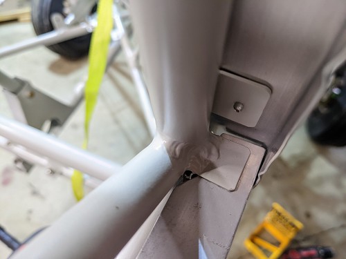
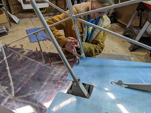
Working on expanding the control horn on the aileron
The heim joint is too wide. Mark said at the factory now they are creating two joggles in the countrol horn on both sides to expand it to fit the wider heim join. I need to do that on my kit.

One bend made, now to bend it back in further out to make it 90 degrees again.

Friday, February 25, 2022
Time: 3h
- Spoke with Dave at Wentworth Aircraft. He is getting me two magneto gears shipped via UPS.
- Spoke with Janina at Better Aircraft Fabric for a quote on fabric, glues, tools for the LSA.
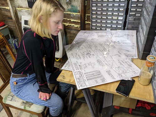
- Spent time studying plans on how the control system works inside the wing.
- Removed wing tank.
- Unpacked aileron.
- Test fit aileron bellcrank.
- Test fit aileron, turns out we do not have the correct heim joint.
Photo Stream
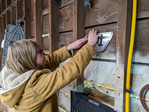
Hanging the R & B Aircraft Label
It was an aluminum label that was on the crate for the O-200 engine that came from Bob Barrows for the Bearhawk.
Removing the tank from the right wing
Applying our first viz-torque

Anne finishing torque seal on all bolts for tank straps

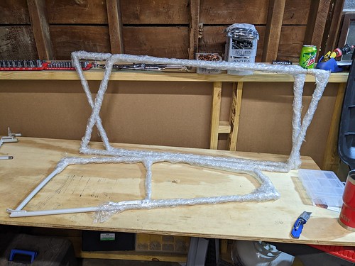
Unpacking the aileron

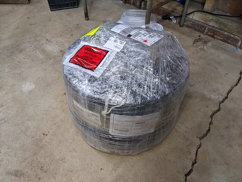
Bearhawk's sure come packaged well.
This was in several sheets of styro-foam, then attached to the wing, which was inside of a steel crate. Get it all out of that, and here it is wrapped in bubble wrap.

Test fitting/visualizing the aileron control system in the wing

Viz-Torque on the tank straps

Thursday, February 24, 2022
Time: 3h
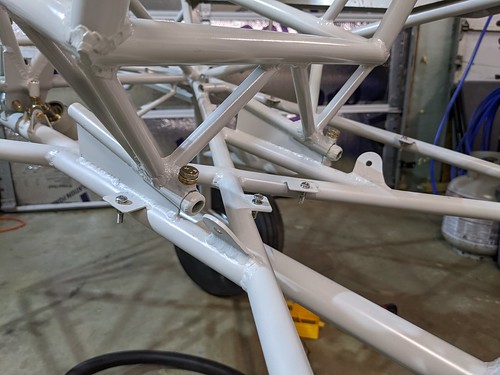
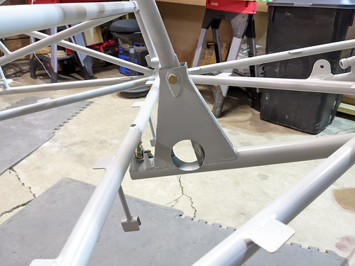
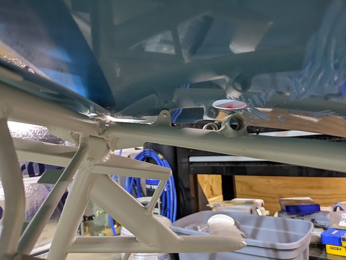
- Drilled final hole for engine mount through firewall.
- Drew outlines of where engine mount will penetrate the firewall.
- Fit and install engine mount
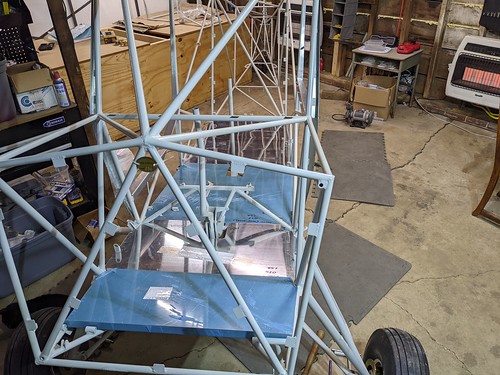
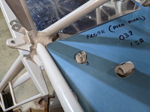
- Final fit on remaining floors (2 front most)
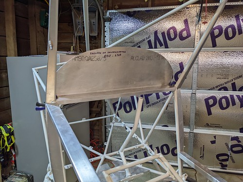
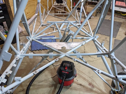
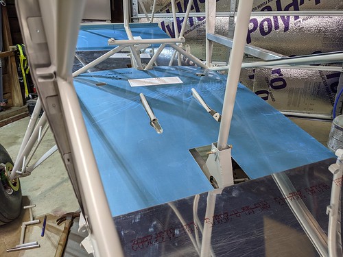
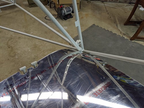
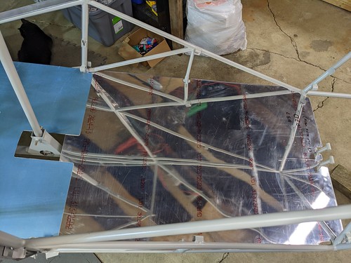
- Built sticks to prop open wing
- Proped open wing
- Studied the plans to see how control systems work, cables are routed, etc.
Photo Stream
Expanding holes to allow engine mount to pass through firewall and contact fuselage
The firewall is not sandwiched between the engine mount and fuselage, instead it is mounted via tabs to the fuselage. The holes where the engine mount would come into contact with the firewall are expanded slightly to allow the engine mount to mount directly against the fuselage.
Firewall trimmed to allow engine mount to pass through for engine mount to fuselage direct contact

Prop open the bottom skin for working in the wing

Wednesday, February 23, 2022
Time: 3h
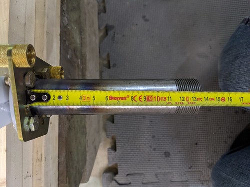
- Looked at left wheel, it is wobbly compared to right wheel. The left axle is 136mm in length and thread starts at 119mm. The right axle is 137mm in length and thread starts at 116mm. This is enough that the axle nut bottoms out on the non-threaded part of the axle, thus it can not be tightened enough. Mark is going to send out some spacer material that I can cut to the proper size.
- With additional hardware I received, I was able to put in the forth bolt/nut on the brake caliper to landing gear leg. The forth nut had to be an AN364, an AN365 did not fit. I also had to grind it down slightly on one edge, as I did the washer as well.
- Unpacked firewall, studied how that will be installed.
- Cleaned holes for engine mount on fuselage side.
- Test fit firewall.
- Drilled firewall tabs and match drilled to firewall.
Photo Stream
Forth bolt in place
3 bolts the AN365 fits fine, but for the forth I needed an AN364, which I now have. Did the same for the other landing gear.
Debugging wheel wobble issue

Left wheel, you can see the problem.
Thread stops before it hits the spacer.

Other Axel
Notice the where the thread starts vs. the other measurement picture.
Sam working on re-installing another floor
We are putting the screws in by hand initially to make sure things fit well. On this floor, 5 needed a little filing in the hole to make things nice and smooth.

Test fitting the firewall
Three engine mount holes were pre-drilled in the firewall. This was enough to get things aligned very easily.

Drilling out the firewall tabs
Since some things are going to be mounted on the firewall, we decided to attach with AN3 bolts, thus drilling things out to 3/16.

Sam getting some experience drilling through steel
Building our Zenith, we had very few steel parts. Drilling steel and aluminum is a different ballgame :-)

Firewall is match drilled
Need to drill out location of engine mount and debur yet.

A live trap for the skunk(s) that made a home under our garage
If you are part of the Bearhawk Builders forum, you know my building of the plane has been interupted by the awesome smell of a skunk who decided to make his home below my garage (work shop).
Today a company came out to set up some live traps and hopefully take care of the problem for me.

Tuesday, February 22, 2022
Time: 4h
- Documented pin information for TY-92 and TT-22 modules and control heads
- Drilled out temporary pop rivets in bottom skin to take a peek
- Drilled horizontal holes through rear seat attachment for 4 quick release seat positions
- Reinstalled rear/cargo floor, filing 4 holes that were not exactly in line, only by a smidgen
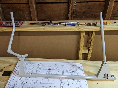
Pilot Seat Frame
I did not care for the bolt type locking mechanism that the LSA uses. It requires tools to change the position of the seat. It also required some very precise drilling and tapping. I decided to not use the nut welded to the top of the rear seat mounting tube but instead drill a horizontal hole through the entire bottom seat mounting tube. I then drilled four stop position holes in the fuselage rear seat mounting tubes. These holes are drilled to 1/4" which will fit a variety of stainless steel quick release clips, such as Ball Locking Pin.
Photo Stream
Wing is out of its crate and temp shipping pop rivets have been drilled out.

Peeking at the wing now that we have it out of its crate

More wing peeking
Need to inspect all bolts/nuts for proper size and torque.

Peeking under the skin
Not really doing work, just peeking under the skin to see what type of work is upcoming.

Pilot hole drilled in rear pilot seat mounting tube

Doing my best to drill 90 degrees to everything
I have a guide to help me do this, but the place I am drilling had too many angles around it and welds coming close to where I was drilling, so I had to eyeball it.

Sam is removing all the screws from the floor board mounts
We put screws in every one making sure that we could screw them into the rivnuts by hand. We had 4 that were damaged during installation. They had to be replaced.
If we couldn't screw the screw in by hand and freely, then we decided the threads were damaged during installation and replaced them.

Drilling pilot holes for the four mounting positions
I drilled the rear hole first and made it as far back as possible. I then drilled the front most position. I then used a common fan tool to quick mark the two positions between the front and rear most positions.
Drilling some holes for the seat locking mechanism
Locking mechanism for pilot seat adjustment
These pins are just place holders that I happened to have for another item. I like the ability to adjust the seat without tools vs the AN4 bolt that the mechanism was built/designed for.

Monday, February 21, 2022
Time: 4.5h
- Worked on wiring digram
- Worked on designing the panel
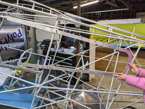
- Removed one wing from the crate
Photo Stream
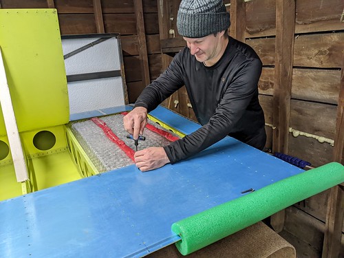
Removing one wing from the crate
Will be going on the table in the shop to begin work on it. The other wing will remain crated until this wing is complete and goes to the hangar.

Sunday, February 20, 2022
Time: 3h
- Worked on wiring plan
- Secured top stringer
- Secured left and right top side stringers
- Secured left and right bottom side stringers
- Secured bottom stringers
Photo Stream
Top and Right sides gets a rivet in the front, Bottom and Left sides in the back
Each C bracket gets two rivets. If I center them, however, the rivets will hit in the middle. Thus, they are offset.

Used a spring punch to make a little hole to capture the drill bit.
Without this, the bit will wander around the metal, where it will wind up no one knows :-/

Deburring is important
You don't want any burs that work themselves loose in time, then make your rivet loose when it breaks free.

Using the punch to mark a hole

Saturday, February 19, 2022
Time: 2h
- Cut front control stick to proper height
- Temporarily installed front control stick grip
- Cut and fit left and right upper stringers
- Cut and fit bottom stringers
This build day was cut short. Skunks built a home under my garage. After talking with some people I learned it was probably temporary. I went inside to look at some information on the computer and when I came out the garage was unbearable with the smell of skunk.
So, gotta get the skunk situation taken care of before I continue building.
Photo Stream
Trimming the pilot control stick
It comes too long, once you know what grip you are going to use, then measure and cut.
Control stick reinstalled with the grip just slid into position
So I can play of course :-)

Left upper side stringer fit

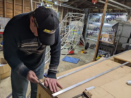
Right Lower Stringer clamped into place for marking
The stringers do bend slightly as they go to the tail. There was a decent amount of pressure on this front mount.
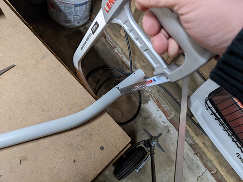
Scrap stringer material that I practiced bending on
The two bottom stringers at the rear do not terminate into the fuselage. Thus, they need some type of relief for the fabric so it is not up against the trailing edge of the stringer.
After playing with cutting the end at an angle, crushing the end a tad and then bending, and then just bending, I liked the look and consistency of the later. No prep, I just carefully took a conduit pipe bender to the rear.

Bottom view of the bottom rear stringer bend
I think it came out pretty good!
The two rear bottom stringers bent

All the stringers are in place
None are drilled or fixed in place yet.

Friday, February 18, 2022
Time: 2h
- Researched SDS Ignition, SureFly, ElectroAir and E-mags for an ignition source. Decided on E-mags P model and ordered. ETA March 18th.
- Cut, Fit, Cleaned up lower side right and left stringers
Photo Stream
Notching out the front of the lower right side stringer

Cutting the rear off the lower side left stringer

Front lower left stringer fit
Left lower rear stringer fit

Lower stringers fit
They are not yet attached. Just fit and clamped into place right now. I'll wait until I have all stringers fit, then attach.

Right front lower stringer fit
Note, the left and right front lower fits were slightly different. I did the left first then used it as a template, and that didn't work. Luckily there is a lot extra on these stringers, so I had plenty left to cut off the front area I notched out and do it again.
Lower left rear stringer fit

Thursday, February 17, 2022
Time: 2.5h
- Cut to length and test fit top stringer
- Practiced bending a string (excess from cut top stringer) for the rear two bottom stringers
- Researched and figured out how to handle side stringers at the door frame
- Researched and figured out how to handle bottom stringers at the front where the rear of the boot cowling will be
- Worked with Franz Lamers at MGL for my Xtreme EFIS. It was not remembering which screen you were last on between power on/off restarts. Turns out the internal CR-2032 battery was dead. Replaced it and all is now working properly.
Photo Stream
Inspect stringers
Before fitting any stringers, we inspected them and based on a little damage decided which one should go where and in what orientation.
Turns out only 1 of the 7 had any real damage, this is a picture of one of the three or four places that were bad. Luckily it was all on one side and mostly to one end. So we chose it for the top stringer, the one that would be trimmed the most. Cut off most of the damage, but one spot remained. We put it inward, and the best side outward towards the fabric.
Cut and fit the top stringer, figuring out the side stringers
Marking the top string a tad long, will file to fit.

Filing top stringer to fit
Figuring how the stringers fit in various places.
Most places were self-explanatory, but the ends at the tail were a bit different than some videos I've seen, and we weren't too sure around the door. But, we got it all figured out!
Cleaning up a practice bend
This was the piece we cut off the top stringer. We crushed one side, used a conduit pipe bender to bend it upward. This needs to be done on the two bottom stringers at the rear.
The bending job didn't turn out as nice as I had hoped, so we are cleaning things up a bit on a Scotch Bright wheel.

The end result
Not the prettiest, but it's smooth and I think the fabric would be happy with it. We are going to bend the other side of this scrap to try again before bending one for real.

Wednesday, February 16, 2022
Time: 2.5h
- Researched exhaust systems for the O-200. Talked with Clint at Vetterman Exhaust for a bit. Wound up purchasing their system with cross-over pipes, two mufflers, baffling on both, one for carb heat and another for cabin heat.
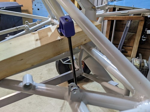
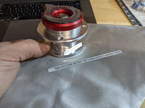
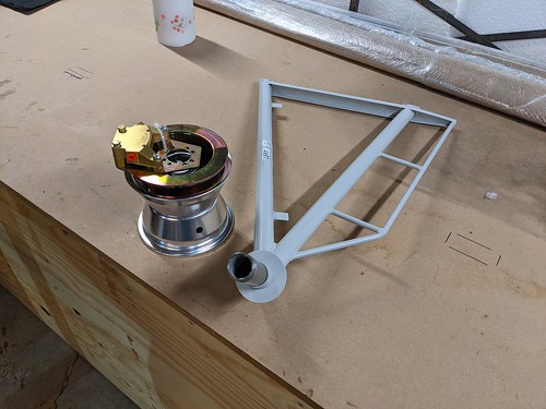
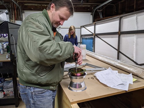
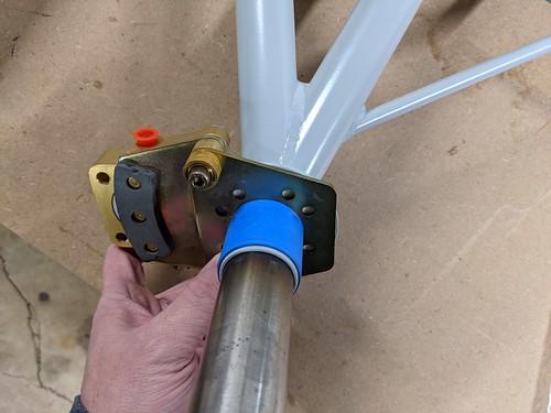
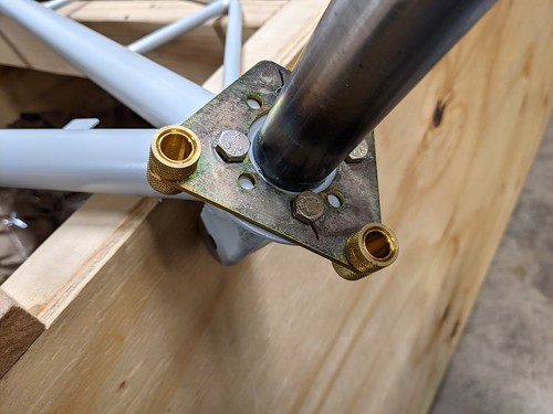
- Began work to fit fuel selector valve. Turns out the bracket supplied is too tall. The valve contruction changed making the valve actually shorter. Thus the bracket needs to be modified.
Photo Stream
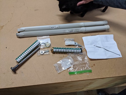
Gathering parts for fuel selector assembly

Bracket to Valve height mismatch

Expanding the fuel selector mount hole a tad to fit the valve
Valve now seats in main support bracket
Tuesday, February 15, 2022
Time: 3h
- Reserved 67BH for the build
- Spoke with Bob Barrows about weight and balance using light weight O-200, carbon fiber prop, minimal instruments, carbon fiber nose bowl, light weight battery, etc... He said things will be fine that his C-85 is about 30 pounds lighter than my O-200 and no issues there.
- Slightly trimmed instrument panel so it would fit, not working on the panel right now just wanted to see it sitting there :-)
- Drilled and tapped rear most seat stops.
- Mounted the door simply to get an idea how well it swings, what the clearance is, etc.
- Mounted the front most floor, wrapped a few straps around the front seat and tossed on some thin cushions to get an idea of where I may have the seat set for myself. All the way back is probably too far, but one from the rear most setting will probably be just right for me.
Seat Stops
The LSA has bolts welded to the seat frame on the rear slides. The plans then show four holes drilled into the rails tha the seat slides on. I am not overly excited about this method of an adjustable seat. It is simple and light weight but is it functional enough for me.
I was unsure if the holes drilled should be tapped or not. I tapped them. Not tapping them would be easier, but if they are not tapped then I am afraid that the bolt threads that protrude into the lower seat rail will be damaged in time and thus not back out of the bolt welded to the seat itself.
Photo Stream
Bolts welded to the rear seat slides
Instrument Panel in place to get an idea of forward visibility with various seat locations
Clamping the seat into position while I mark where to drill the holes for seat stop
Rear most seat stop holes drilled, tapped, and bolts actually thread in!
Monday, February 14, 2022
Time: 3.5h
- Removed Rivet Nut that was damaged during installation. Didn't realize it was damaged until I tried to put a screw in, it then got tight and stuck when backing it out. That turned into a big job!
- Finished installing rivnuts for all floor board mounts
- Checked to ensure we have matching pairs for horizontal stab, elevator, wing tips and window frames
- Played with the door a little, created (but did not install) the latch
Photo Stream
Drilling out a rivnut
Out of 48, 5 were bad, those 5 were within the first 10 that I pulled. I made a few adjustments to the rivet nut gun (lightened up the pull) and the remaining 38 were all fine.
All rivnuts for the floor boards are installed!
I placed a screw in each rivnut by hand. If it didn't go in by hand, I removed the rivnut and pulled another. One of the bad rivnut's that I had I could not remove the screw. It began dragging and then backing it back out was nearly impossible. In fact, I broke a screw in half twisting it back out. I had to drill for a while on that one.
Completed Rivnut Install

Just scoping out the door and window frames
Looking for a short task. We received two left pilot rudder pedals, so wanted to just double check other paired parts since a truck is coming in soon.
How does the door latch work?
Curiosity got the best of us. We did a little assembly, just enough to see how it works.

Check for left and right window frames

Sunday, February 13, 2022
Time: 3h
- Purchased a better, higher quality Rivnut tool from Summit Racing (they are local to me)
- Installed one rivnut manually and created a drilling template. We did this from underneath the fuselage and that was not a comfortable position to work. Thus the template allowed us to drill the remaining tabs from above.
- Drilled out all floor boards tabs using our template and a #30 drill bit.
- Reinstalled floor boards and clamped in place.
- Match drilled floor boards to floor tabs. We used a #30 drill bit so we could cleco the floor boards in place as we drilled to ensure no movement.
- Expanded holes in floor boards to accept an 8-32 screw.
- Expanded holes in the floor board mounting tabs to accept the 8-32 rivnut.
- Deburred all holes, mounting tabs and floor boards.
Photo Stream
Anne followed up and completed the hole
Drilling through the steel tabs took long enough that we figured one person to mark the hold, start it so the drill didn't walk, then move on while another finishes the job. This worked well.
Using a template, I am starting a hole through each of the floor mounting tabs
We are using Rivnuts to mount our floor boards. We manually positioned one from underneath the fuselage to ensure proper clearance and edge distance. From that we then made a template to drill from above, which was a much more comfortable way of drilling.

The end game (well, for the hole at least :-D)
Once all the holes were drilled through the mounting tabs, floor was reinstalled, clamped and then we drilled from the bottom up.
The holes we made in the mounting tabs was a hole suitable for the 8-32 machine screw we are using for mounting. Once the floor boards are drilled, we will then debur the sheet metal and expand the holes in the mounting tabs to accept the rivnut.
Floor all drilled
Next up, deburring aluminum, expanding mounting tab holes, deburring those, and installing rivnuts.

Some deburring work going on

Expanding the mounting tab holes to accept the rivnuts
Saturday, February 12, 2022
Time: 5h
- Installed Control Stick Assembly
- Fit floor boards
- Broke my 10-24 Rivet Nut head :-(
Working Notes
Working on the control stick assembly. When assembling, lay the interconnect tube inside the torque tube, install the front stick first and connect it to the interconnect tube. Then slide in the rear stick enough to connect the interconnect tube. Then install the main pivot bolt in the rear stick.
Also, I had to remove one shock to slide the control tube through. I could not find a way to twist it through otherwise, maybe it exists, but I couldn't find it.
It took much longer than anticipated to clean the holes out so the bolts slid into the tubes nicely. I think I need to invest in some reamers. The sandpaper trick is too time consuming and I always wind up ripping up the sand paper.
Bolts
- Interconnect Tube calls for an AN3-5A with a AN364 (Shear Elastic Locking Nut). The plans also mention shortnening. Need to purchase some AN364's
- Control sticks to Torque tube, AN4-21 is too small. AN-24 is too large. Need to measure and purchase the correct AN bolts.
- Torque Tube to Fuselage AN3-10A.
Photo Stream
Collected the main parts for the primary control assembly

Test fit everything before putting mounting to the fuselage
Screwing in one of the tie rod ends where the torque tube will hang from

Torque Tube and Sticks are installed!
All of this is test fitting at this point. Nuts are coming :-)

Another view of the hung control assembly

Rear view of the control assembly, again nuts are coming :-)
Test fitting the floor boards (front)
Test fitting the floor boards (2nd from front)
Here you can see the front floor board needs a little trimming (lip resting near the landing gear mount. Also, the 3rd from the front does not sit down all the way.
Hitting the rear passenger master cylinder mount
I ordered mine with brakes for the rear passenger. I am unsure if the mounts are there for all models and just the pedals and cylinders are part of the addition or not. Anyway, my floor board did not have cut outs for the rear passenger brake cylinder mounts. Had to mark, drill, then shape.
Another view of the 3rd floor board before fitting
Baggage compartment floor board
As you can see, the rear of it needs some trim work to make it sit flat.

Main culprit for the baggage floor not fitting properly
Rough trimming
After I was close, I finished things up with a Scotch Bright wheel to make nice edges and transitions.

All floor boards are now fitting properly!
Close up of the passenger brake cylinder mounts now protruding the floor board
Proper fit of the baggage compartment floor
Clamping the floor board in place for drilling

Making the first hole for the floor board

Installing a rivet nut
I had the depth set wrong and stripped the head on my cheap rivet nut puller :-/ That put an end to the evening of installing the floor boards...
Friday, February 11, 2022
Time: 5h
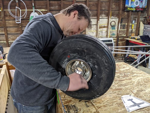
- Mounted right tire
- Packed the wheel bearings with grease
- Installed Landing Gear Legs
- Test fit rudder pedals
When I purchased the kit, there was what I know to be an incomplete hardware kit available from Wicks. I did not realize how incomplete it was until I started. I am going to try to keep an accurate log of all hardware that I use during this build for others to use as a guide/reference/suggestion. Most of the work done today was fitting, cleaning holes, figuring out the right bolt sizes, test fitting, etc... I will have to replace 4 bolts in the rudder pedals and 8 bolts in the landing gear, but that should be pretty easy now that all the prep work was done.
When I went to test fit the rudder pedals I realized I have two pilot left pedals, not a left and right pair. A quick text message to Mark had that solved. A truck is coming in from the factory in about three weeks and a right rudder pedal will be delivered to me.
Photo Stream
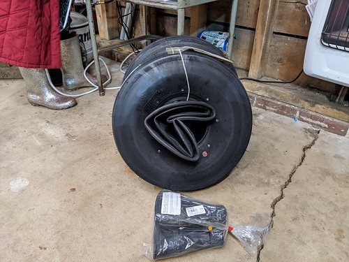
One wheel left to mount
Tube and Tire mounted!
The white stuff is baby powder that I spread all over the inside of the tire and the tube to make installation easier.

Installing the brake discs
Removing the crating bracket from the landing gear mount

Installing the left landing gear

Cleaning the holes for the shock mount
The metal parts are painted and often times paint inside the hole makes it a tight (or impossible) fit for the bolt. A little fine sand paper wrapped around a screw driver of the appropriate size does the trick.

Test fitting the rudder pedals
When doing this it was realized that we have two left pilot rudder pedals. No right. For the passenger, we had a proper pair.

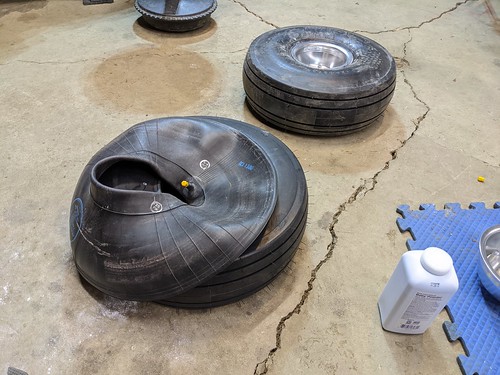
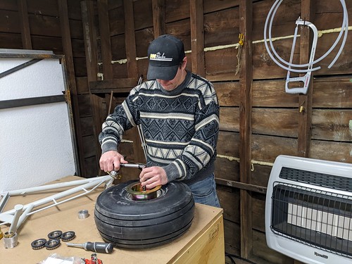
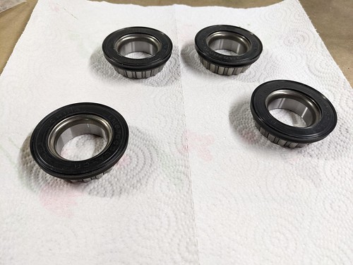
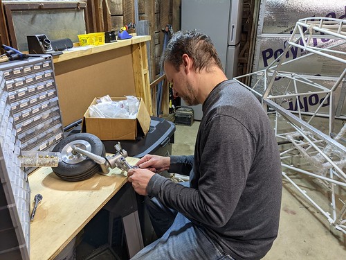
Getting ready to grease the wheel bearings
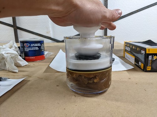
Loading the wheel bearing grease packer

Packing the bearings
I purchased this from my local O'Reilly Auto Parts store. I was going to pack by hand bug figured that packing will be part of routine maintenance, so why not make things easy on myself.
It's on it's gear!

Family posing next this milestone
When building the Zenith Cruzer, it was many months until the plane was standing on it's own gear. This isn't to say the Bearhawk is better or worse, just a different type of build. None-the-less, the family (and myself) only knows the Zenith build, so seeing it on it's gear within the first week was pretty fun!

Tuesday, February 8, 2022
Time: 3h
- Drilled and installed right caliper mount to the landing gear.
- The inner wheel spacer for the LSA did not quite have enough clearance for the AN4 bolt heads. I had to take the Dremel tool and grind a little out for them to fit properly.
- Installed the tire and tube on one wheel.
- Installed the tail wheel.
Photo Stream
Tires and tubes arrived today from Aircraft Spruce
Living in Ohio, when ordering from Aircraft Spruce if the Pennsylvania warehouse has it in stock it arrives next day with normal shipping!
Tires and tubes
Matco wheels and brakes as delivered

How I hold the brake caliper bracket in place while drilling
Expand cut-outs in the inner wheel spacer
Take apart the hubs so we can mount the tires

Installing the tail spring into the tail wheel
Powder up the tube to make it easier to install

Install the tube in the tire

Filled the tube up to position it inside of the tire

Installed both rim halfs, now torque it down properly
Tailwheel is installed!

Monday, February 7, 2022
Time: 2h
- Installed the left brake caliper onto the landing gear leg.
Photo Stream
Collecting pieces for left landing gear
Test fit larger spacers to provide proper brake disc location
Tape up the spacer to provide a centering bushing to drill holes for brake caliper installation
In order to center the caliper around the axel properly, I took the spacer on the axel (not used in my case) and wrapped blue tape around it until the brake caliper mount fit snuggly around it. Then simply slide it on the axel and it's properly centered.
Brake caliper is properly centered around axel
Three of the four bolts in place
Sunday, February 6, 2022
Time: 1h
- Built both landing gear shocks.
Photo Stream
Parts collected for shocks
Plunger cleaned up

Inner O-ring installed in top cap

Test fit pieces
Compress spring so assembly fits in shock casing with room to install snap ring

Install snap ring
Two completed shocks

2021
In 2020 and 2021 I built a Zenith CH-750 Cruzer with my girls. I assumed it would be an enjoyable process but that 1/2 way through it I would be looking forward to the end. This was not so. Towards the end of the project we were all a bit sad to see it coming to a close.
What did we do then? We set out to build another, this time a Bearhawk LSA. We had planned on starting the Bearhawk LSA in the fall of 2021 but we finished the Zenith later than anticipated and flight testing continued into the fall on the Cruzer. Thus the Bearhawk was put on hold.
Nonetheless, we did a lot of thinking, research, planning, and purchasing in 2021 for the Bearhawk so we could start 2022 ready to go.

March 2021
March was the month of much planning, big orders and the start of waiting...
March 26, 2022
Ordered the Bob Barrows O-200
Purchased the base Continental O-200 with:
- 8.5 compression ratio
- New Pistons
- Rebuilt Cam and Tappets
- MA3SPA Carburetor
- Lightweight Starter
- Lightweight Alternator
- Lightweight Oil Reservoir
- No magnetos as I'll be using E-mags
March 17, 2021
Ordered my Bearkhawk LSA Kit
Includes several options and delivery
- Clear Windshield
- Brake Cylinders
- Hardware Package
- 6" Aircraft Rims (tires are self purchase)
- Curtis Drain Valves
- SPRL fuel selector
- 2 Throttle Quadrants
- Rear Rudder Pedals
- Carbon Fiber Wing Tips
- Carbon Fiber Nose Bowl
- Tail Wires
Outstanding
Please see side bar for Outstanding Decisions to be made.
- ELT GPS Input: In an emergency electrical fire, if I turn off my master switch, the EFIS will go off, thus the GPS receiver will turn off, thus my ELT will know and transmit that location in the event of an accident and it is tripped.
One or Two MGL Xtreme's?
Thoughts
The main instrument in my Bearhawk is going to be the MGL Xtreme Mini EFIS. This device is a combination device including
- Airspeed
- Altimeter
- Vertical Speed
- Artifical Horizon
- Turn and Bank Indicator
- Slip/Skid Ball
- Timer
- Navigation
- Full EMS
I can split the screen between the primary flight instruments and a mini-EMS display. The question is does it make it too cramped on the screen to be of use. That answer is no, but it does make it harder to read as some metrics are made smaller, such as the Airspeed and Altitude. So, is it enough of a reduction in size and increase in clutter to install a second unit that would be a dedicated EMS display?
Discussion
February 16, 2022
I have been speaking to Franz Lamers at MGL in regards to two Xtreme's. My Xtreme does not remember what screen it was last on and I was concerned if I have to set each EFIS each time I start the aircraft. As it turns out the Xtreme has a CR2032 battery that remembers state. My Xtreme seems to have a dead battery. So, if I have two Xtreme EFIS units, I can set one as my EFIS and the other to EMS. It should remember.
Decision
Undecided
Paint Scheme
Deciding on the paint scheme is something that can typically be put off for some time but I have decided to cover the airplane with Oratex. This pushes the need to decide on a paint scheme earlier because:
- Oratex comes in the color you wish, you do not paint it
- The color I wish may need to be manufactured, thus some lead time
- Parts of the interior will be covered much earlier than the exterior and I do not wish to place multiple orders
- I believe I will use Oratex to cover the seat base and back. I need to do this sooner than later so I can get my seats off to have upholstery created. Again, see #3.
Propeller
Thoughts
Mark Goldberg recommends the Catto 72x44" composite propeller. Hartzel is in Ohio, where I am based, kinda nice to support locals. I do like my DUC that is on the Zenith, the 3-bladed design making for a quieter environment (inside and outside) and the ability to adjust the pitch. The 3-bladed design also has a smaller overall length due to an additional blade, thus has higher ground clerance.
Manufacturer Research
March 25, 2021
Catto responded that the 72x44" is a great all around performing propeller. It would cost $3,100 with nickel leading edge. A small adapter is necessary for the O-200-D. The spinner would be $515.00 cut, fit and ready to install. Lead time was August/September.
February 10, 2022
I sent an information request to Hartzell and DUC.
- Hartzell only makes constant speed propellers, I did not realize that. They are out. They did respond via email pretty quickly though, that was nice!
- Catto got back with me, price was raised to $3,300.00 and lead time is June.
February 14, 2022
Gaeton suggests either a Swirl-2-R or Flash-R. He has a 2 week lead time and will deliver a quote by the end of the day.
February 16, 2022
Sensenich Propellers makes a ground adjustable composite prop that may be of interest, 2 Blade Continental O-200/Lycoming O-235 Ground Adjustable STOL Propeller
2 vs. 3 blades
Catto Propellers states: "From a performance standpoint the 2 Bladed and 3 Bladed very similar, almost equivalent. The 3 Bladed propeller is smoother due to it’s ability to distribute the power pulses from the engine."
Lighting
Landing/Taxi Lights
I have two from my Zenith build. I originally purchased two wing kit lights and was going to place a landing and taxi light in each wing. I decided to just go with one wing having lights in it, thus I have two extra lights. Those will be what I use for the Landing/Taxi light on the BearHawk
They are the SunSpot LED Landing Lights.
Position/Navigation/Strobe Lights
I like the AeroLED Pulsar lights that are on my Zenith. They are pricy, but I have not looked at others. So, do some market research.
AeroLED
$996.00 a pair
https://www.aircraftspruce.com/catalog/elpages/aeroleds_11-17138.php
Kuntzleman LED Aircraft Lighting System
This is much cheaper than AeroLED Pulsar lights ($410.00 vs. $996.00). The Aircraft Spruce page says that the are nightime approved, but says "according to the manufacturer." Seems a bit sketchy.
$410.00 a pair
February 25, 2022
I sent an email to KE Strobes and got a response within an hour from Dick Kuntzleman. He said that the Nav/Position/Strobe lights are legal for night flight in an experimental aircraft.
Beacon Light?
Do I need a beacon light if I have the Position/Nav/Strobe Lights? Currently on my Zenith before starting the engine I turn on my strobes as an indicator that the engine is going to soon be running or running (in addition to calling clear of course). Does it make sense to have a Beacon light?
See
- FAR 91.205 - Airworthiness Certificates
- FAR 91.209
- AC 20-30B - Installation requirements
Completed
Please see side bar for Completed Decisions to be made.
Tires?
Thoughts
When thinking about a "bush" plane, often the first though is the bigger the better, 27", or why not just go to 31"? These big tires are certainly best when you begin to get into true off airport work, landing in rough fields, gravel bars with mini-boulders, etc. but am I really going to do that?
It is said that good old 6.00-6 tires can handle 95% of what most people fly on, and certainly 100% of what is labeled as an airport, even back country airports. The next most common size is 8.00-6 but this jump adds considerable weight and aerodynamic drag.
Decision: February 7, 2022
Ultimately after reading a few reports and resources, I decided to go with the less common, but still easily acquired, 7.00-6 tire. These tires provide a little more margin over the 6.00-6 tires yet introduce no measurable weight or aerodynamic drag.
The final tire I purchased was:
Ignition Source?
Decision (February 18, 2022)
E-mags. Simple magneto interface/install, generates its own power after it hits 800 RPM, so no dependency on battery.
Thoughts
I declined to use Bendix mags that Bob suggested. I believe I can have a smoother running, more fuel efficient system using E-mags of some sorts. I know there are a few options, but unsure of all options, pros and/or cons.
This decision should be made sooner than later because E-mags, as of right now (February 8, 2022), have a 2 month back-order time listed. I would hate to have the engine ready to run but no ignition source!
Options
E-mags
These contain a built in generator that supplies it's own power once engine RPM reaches 800 RPM. I can run automotive spark plugs. I spoke with Jerry, who installed them on a Lycoming engine for his RV4. He really likes them, the maintenance, the cost of automotive spark plugs, and he gets better fuel economy.
February 18, 2022
I reached out to E-mags asking about cost for an entire setup for my Contientnal O-200, and also lead time. Aircraft Spruce currently says No Stock.
Brad responded within an hour with a quote and lead time. Lead time is 3-4 weeks, best guess he said. I asked for a little clarification.
SureFly
https://www.surefly.aero/
It is 100% dependent upon battery power. All references I see speak of replacing one magneto, not two. This is also for Certified aircraft. I am unsure if the rules/suggestion is different for Experimental aircraft.
SureFly is out, it is designed for and targets Certified aircraft.
SDS Ignition
This is a fully electronic ignition system. http://www.sdsefi.com/cpi.htm
Package seems more complex than just drop-in mag replacement. There is a panel mounted control head. It will allow the use of automotive spark plugs, wiring harness and plug adapters are included in the kit. Has the ability to switch profile based on 100LL and mogas.
February 18, 2022
I reached out to them asking about what exactly I would need, cost, and lead time. They responded within minutes. That was nice. Lead time is 2 weeks and price is better than the others. I need to do some reading.